
High-speed extrusion and converting lines generate continuous edge trim. When operators remove scrap manually, trim accumulates around slitters and winders, interrupting production and increasing safety risk. Automated scrap transport solves this challenge. A waste material conveying machine captures trim at the source and moves it directly to recycling or densification equipment, maintaining a steady material flow.
Manufacturers such as JTW International, which engineers trim conveying and densification systems for plastics processing plants, design solutions that integrate scrap handling with production lines. Engineers typically evaluate two technologies when selecting trim removal infrastructure: venturi inducer systems and cutter-blower systems.
The Operational Cost of Poor Trim Handling
Production Disruptions Caused by Manual Scrap Removal
Edge trim accumulates quickly around slitters and cutting stations. Operators often step in to remove scrap manually when the buildup interferes with product flow.
This approach creates several operational issues that affect both productivity and safety.
Operational consequences
Line interruptions
- Production pauses while operators clear accumulated trim
- Overall equipment effectiveness declines when machines stop frequently
Operator exposure
- Workers approach active cutting or winding equipment
- Scrap removal occurs close to moving rollers and rotating shafts
Material flow disruption
- Loose trim interferes with product winding
- Scrap contaminates finished material rolls
Facilities install industrial conveyor systems for waste to eliminate these interruptions and maintain uninterrupted production.
Recycling Inefficiencies Caused by Irregular Scrap Flow
Manual scrap handling also affects recycling efficiency. When operators collect trim in batches, recycling equipment receives inconsistent material feed.
Recycling challenges that result from irregular scrap flow
- Unstable input to compactors or densifiers
- Inconsistent scrap density and quality
- Increased contamination when material contacts the floor
Automated trim transport stabilizes material flow and supports continuous recycling operations.
How Automated Trim Conveying Systems Work
A waste material conveying machine removes trim directly from production equipment and transports it through pneumatic duct networks using controlled airflow.
These systems operate continuously while production lines remain active. Trim enters the conveying network immediately after separation, preventing accumulation around the line.
Core Components of Trim Conveying Infrastructure
Trim Pickup Points
Pickup inlets appear near locations where trim separates from the product. Typical positions include:
- slitter stations
- extrusion die exits
- winders
- edge trimming equipment
These inlets capture scrap immediately after separation, so trim never reaches the floor.
Pneumatic Conveying Ducts
Duct systems carry trim using airflow produced by blowers or vacuum systems. Air velocity keeps lightweight plastic film or foam suspended within the air stream as material travels toward the receiving unit.
Scrap Receivers
Receivers collect conveyed material before it enters recycling equipment.
Common receiver types include:
- Scrap receivers designed for large material volumes
- Cyclone receivers separating lightweight particles and fluff
- Continuous receivers mounted directly to compactors or densifiers
These receivers maintain controlled scrap flow throughout the recycling process.
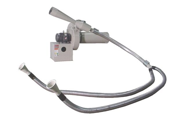
Venturi Inducers: Efficient Trim Removal for Standard Production Lines
Venturi trim inducer systems create suction through airflow acceleration. The pressure difference generated inside the venturi draws trim into the conveying stream.
A cutout and edge trim machine using venturi induction removes scrap effectively in moderate-volume production environments without introducing complex mechanical stages.
Airflow Mechanics of Venturi Induction
Venturi devices operate through a simple airflow principle. Air accelerates through a narrowed passage, which reduces static pressure and generates suction at the trim inlet.
Once trim enters the system, airflow carries material through ductwork toward the receiver.
Typical venturi system components
- venturi inducer unit
- blower and AC motor
- trim inlet connections
- airflow dampers or silencers
This design produces reliable scrap removal while keeping mechanical complexity low.
Typical Applications for Venturi Systems
Venturi systems perform best in environments where scrap generation remains moderate and conveying distances remain manageable.
Production scenarios where venturi systems perform well
- foam extrusion lines
- plastic film converting operations
- single-line manufacturing setups
Venturi-based cutout and edge trim machine maintain consistent scrap flow while allowing plants to integrate trim removal with existing equipment.
JTW International engineers their venturi conveying systems with integrated pickup points and optimized airflow paths so trim removal occurs without disrupting line operation.
Cutter-Blower Systems: Built for High-Volume Scrap Handling
Large converting plants produce higher scrap volumes that exceed the capacity of simple induction systems. Cutter-blower technology addresses these conditions.
These systems function as industrial conveyor systems that transport large scrap volumes across extended plant distances.
How Cutter-Blower Technology Works
Cutter-blower systems perform two coordinated operations that stabilize scrap transport.
Stage 1 – Scrap Reduction
Mechanical cutters reduce trim into smaller fragments. Uniform scrap fragments move more easily through pneumatic ducts and reduce the risk of material blockage.
Stage 2 – Pneumatic Transport
A high-capacity blower pushes reduced scrap through the conveying network toward receivers or recycling equipment.
This process maintains continuous scrap flow across long conveying distances.
Operational Scenarios Where Cutter-Blower Systems Excel
Cutter-blower systems support environments where scrap generation and conveying requirements exceed the capabilities of venturi systems.
Production conditions favoring cutter-blower systems
- high trim generation rates
- multiple trim pickup locations
- long conveying distances across the facility
- centralized recycling infrastructure
Facilities operating several converting lines often implement plant-wide scrap transport systems engineered by companies such as JTW International to maintain consistent trim handling across production areas.
Venturi Inducers vs. Cutter-Blowers: Performance Comparison
Different production environments demand different trim conveying technologies. Selecting the appropriate solution depends on scrap volume, conveying distance, and plant layout.
Technology Comparison
|
Feature |
Venturi Inducer Systems |
Cutter-Blower Systems |
|
Scrap volume capacity |
Moderate |
High |
|
Conveying distance |
Moderate |
Long |
|
Mechanical complexity |
Low |
Moderate |
|
Ideal plant configuration |
Single-line operations |
Multi-line facilities |
Both technologies function as a cutout and edge trim machine, depending on plant requirements.
Venturi systems offer simple and reliable trim removal in moderate production environments. Cutter-blower systems handle larger scrap streams and extended transport distances.
Engineering Airflow and Scrap Velocity in Trim Conveying Systems
Efficient scrap transport depends on airflow design. Trim must remain suspended within the duct stream throughout the entire conveying distance.
A properly engineered waste material conveyor maintains airflow velocity above the settling speed of the conveyed material.
Key Engineering Variables
Air Velocity
Air velocity must remain high enough to keep trim suspended inside the duct stream. Low airflow speeds allow material to settle and accumulate inside the conveying ductwork line.
Duct Diameter
Duct sizing affects airflow stability. Oversized ducts reduce air velocity, while undersized ducts increase pressure losses.
Scrap Density
Light foam trim behaves differently from heavier plastic film scrap. Conveying systems must account for these density differences when designing airflow conditions.
Pickup Placement
Pickup inlets must capture trim immediately after separation. Delayed pickup points allow scrap accumulation and disrupt conveying efficiency.
Engineering teams at JTW International design trim conveying systems around these airflow variables to ensure stable scrap transport across production lines.
Integrating Trim Conveying With Recycling Equipment
Automated scrap transport delivers the greatest operational value when integrated directly with recycling equipment.
Trim conveying systems create a continuous material stream that feeds downstream recovery processes.
Downstream Processing Equipment
Densifiers
Densifiers compress foam and film scrap into dense recyclable blocks that simplify storage and shipping.
Compactors
Compactors reduce scrap volume while producing uniform output suitable for recycling markets.
Balers
Balers package plastic scrap into manageable bundles for transport to recycling facilities.
Facilities operating industrial conveyor systems for waste maintain a consistent recycling feed while eliminating manual scrap handling.
Design Factors for Selecting a Trim Removal System
Selecting the correct trim conveying system requires evaluation of several operational variables.
Engineering Criteria
Scrap Volume
The total trim generated per hour determines whether induction or cutter-blower technology provides adequate capacity.
Conveying Distance
Long conveying distances often require stronger airflow systems and mechanical scrap reduction.
Number of Pickup Points
Multiple trim sources increase system complexity and airflow requirements.
Material Characteristics
Foam, film, or mixed substrates influence conveying velocity and duct sizing.
Selecting the correct cutout and edge trim machine configuration ensures stable trim removal while maintaining production efficiency.
Conclusion
High-speed plastics manufacturing environments require stable scrap handling systems that remove trim without interrupting production. Automated trim conveying systems capture scrap at the source and transport material directly to recycling equipment.
Venturi inducer systems perform effectively in moderate-volume applications where conveying distances remain manageable. Cutter-blower systems support higher scrap volumes and extended plant-wide transport requirements.
A properly engineered waste material conveying machine connects production lines with recycling infrastructure and transforms trim waste into a controlled material stream. Facilities implementing industrial conveyor systems for waste improve operational stability, worker safety, and recycling efficiency while maintaining continuous production flow.


Comments